Access Points: Physical Installation & Mounting Hardware
This article describes how to install your Datto Access Point and mount it using included or provided hardware.
Environment 
- Datto Access Points
Description
The physical installation and mounting steps provided in this article apply to all Datto Access Points, as they share the same form factor and include the same mounting hardware.
Physical installation 
Keep the following information in mind when installing your access point:
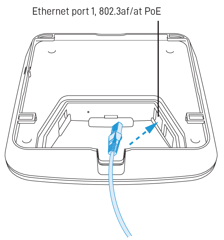
- Datto Access Points requires 802.3af PoE input. Connect to an 802.3af-compatible PoE switch or PoE injector.
- Place the access point in the center of the room and away from any metallic surfaces.
- This access point radiates signal primarily to the front and sides. This access point will only provide limited coverage directly behind it.
- Do not place heavy objects on the access point.
- Install the access point in an area free from strong electromagnetic sources.
- Check the Ethernet cables to ensure a secured connection between the access point and PoE injector or switch.
- Do not install this access point in plenum spaces. Use the ceiling mount instead.
You can use the universal mounting plate to attach it to any solid surface.
-
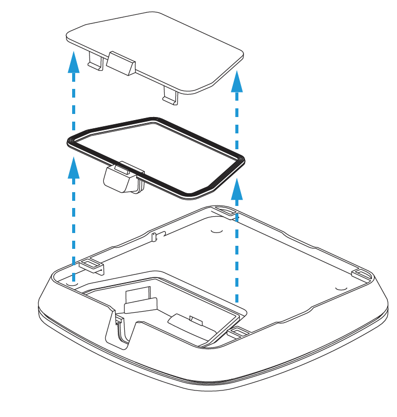
Remove the access point's rear door and seal.
-
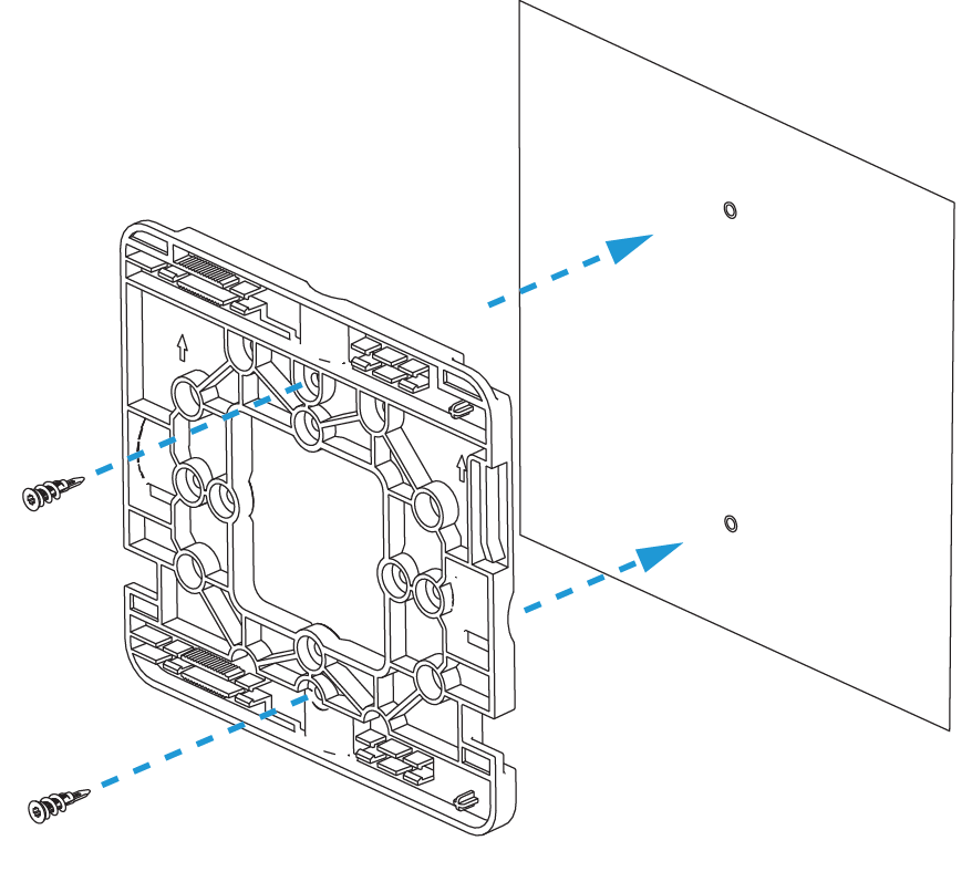
Mount the flat side of the mounting plate to a wall or ceiling.
-
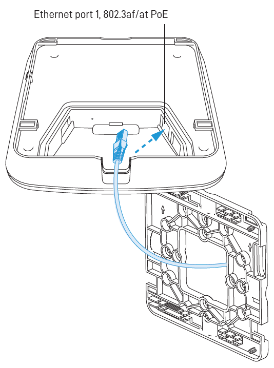
Connect an Ethernet cable to Port 1 on the access point.
-
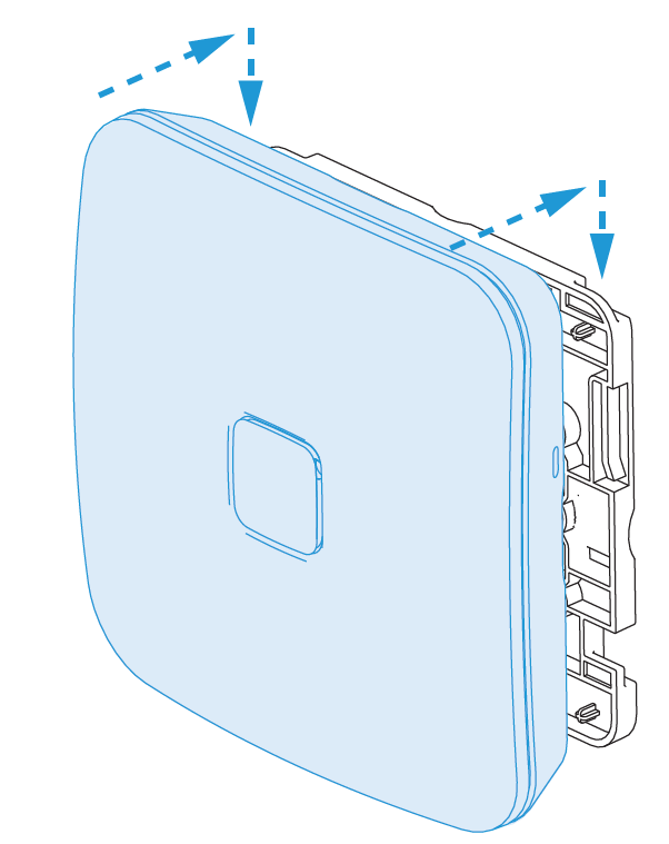
Slide the device down the plate to lock it in place.
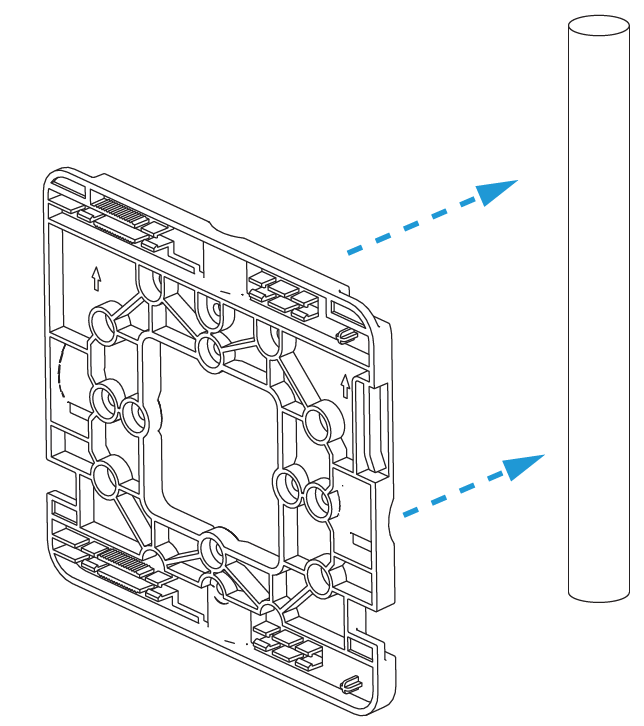
You can configure your access point to mount it outside to any wall or pole. This configuration protects the device against the sun, rain, and dust. Operating temperatures range from 0°C to 50°C.
-
Remove the access point's rear door and seal.

-
Secure the flat side of the mount to an outdoor fixture. Ensure that the arrows on the plate point upwards when mounting.
-
Place the Ethernet cable through the seal and connect it to Port 1 on the access point. Reinstall the seal and back cover.

-
Slide device down the mounting plate to lock it in place.
You can mount this access point to any junction box for secure installations in hotel and resort guest rooms, dorms, care facilities and more.
-
Remove the access point's rear door and seal.

-
Mount the flat side of the mounting plate to a junction box.

-
Connect the included slim Ethernet cable from Port 1 on the access point to the connection in the wall.

-
Slide the device down the plate to lock it in place.

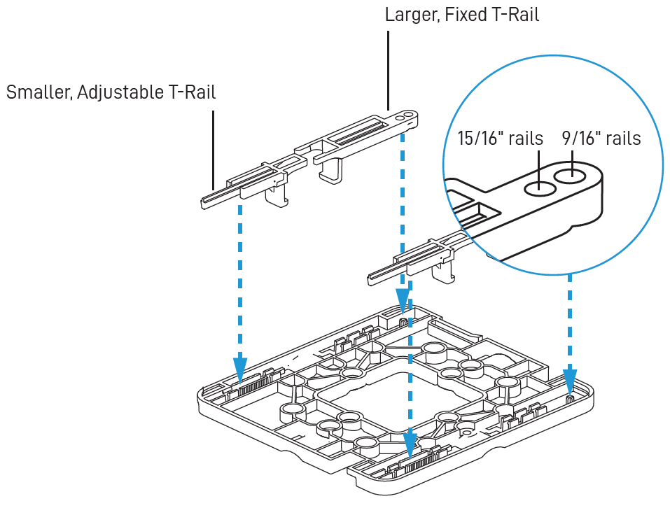
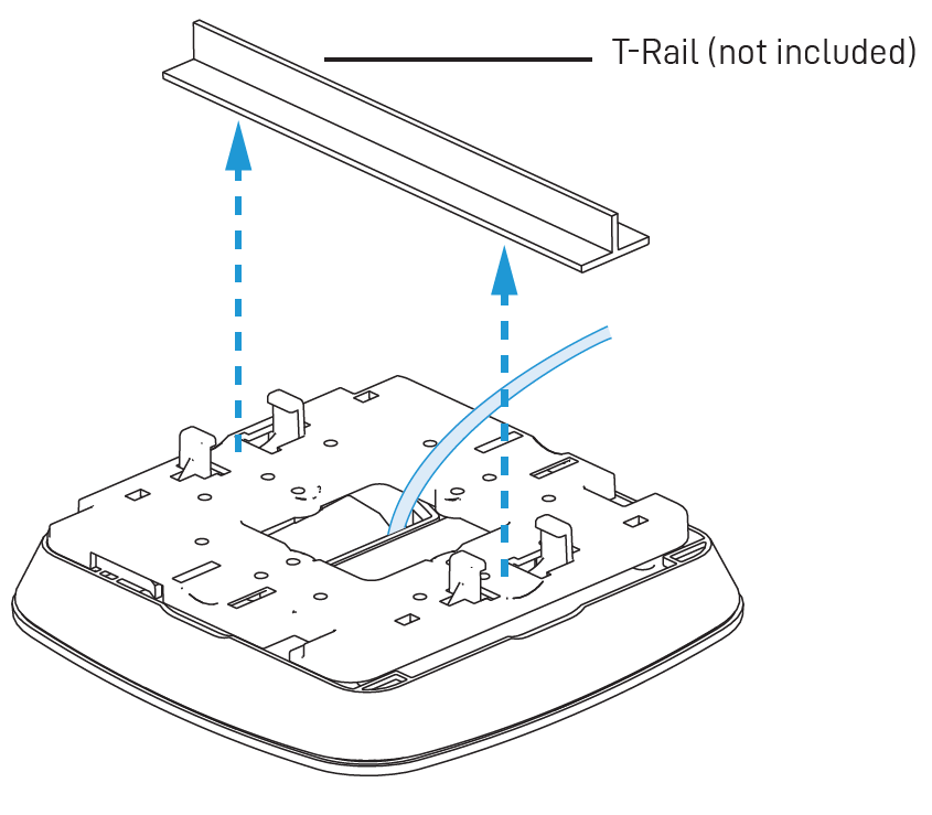
You can use the included T-Rail hardware to attach the access point to a drop ceiling T-Rail or T-Rail system.
-
Remove the access point's rear door and seal.

-
Place all four T-Rail clips onto the mounting plate.
-
Place Ethernet cable through the mount and connect it to Port 1 on the access point. Slide the mount onto the device.
-
Use the adjustable rail clips to tighten the ceiling T-Rail until it is secure.
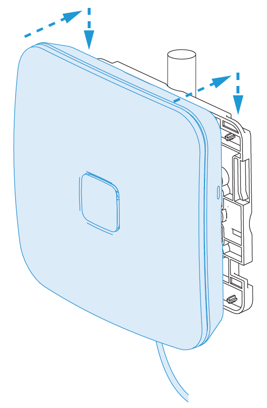
Removing the device
To disengage the device from the mounting bracket, find the oblong pinhole on the side of the access point. Insert a paper clip into the pinhole to disengage the latch, then slide the device off of the mounting bracket. 


