LAN Settings
This article describes how to configure up to four LANs on your Datto Networking Appliance (DNA).
Environment 
- Datto Networking Appliance (DNA)
Description 
The DNA contains 4 physical LAN ports that let you configure up to 4 individual LAN networks. These ports are labeled as 3, 4, 5 and 6 on the back of the DNA.
To manage your LANs, log into the DNA web interface, and click Networks.
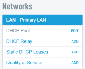
You will see the LAN category displayed in the Networks column of the Manage page.
Index 
- Labeling LANs
- LAN Port Assignment and IP Subnet
- IP Address Conflicts
- DHCP Pool
- DHCP Relay
- Static DHCP Leases (Reservations)
- LAN Site-to-Site VPN access
- Quality of Service (QoS)
- Advanced Options
Labeling LANs 
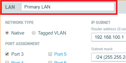
1. Select the desired LAN from the Networks pane. By default, the original LAN is named “Primary LAN.” To use the original LAN, remove this name from the text entry field and enter a new name.
3. Click the Save Changes button.
LAN Port Assignment and IP Subnet 
By default, the DNA comes configured with all 4 LAN ports assigned to one LAN. To add additional LANs, you must first unassign a port from the main LAN.
1. Select the desired LAN from the Networks pane shown in Figure 2.
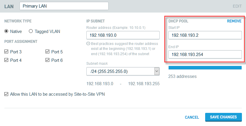
2. In the Network Type section, select Native or Tagged VLAN.
2. In the Port Assignment section, select which ports you would like included for the LAN.
3. In the IP Subnet section, provide the private router address and subnet mask you would like for the LAN. You may use up to a /30 subnet mask.
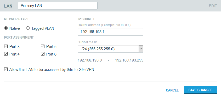
Figure 4: Port assignment settings
4. Click the Save Changes button.
IP Address Conflicts 
If the IP address of a DNA's network interface conflicts with the address of one of its other network interfaces, you will see an IP Address Conflict Detected banner displayed across the device UI. The Network Health card will also display the interface experiencing the conflict.
Click the View button to go to the affected interface's card, where you will see detailed information about the error.
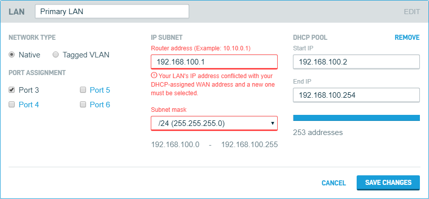
Figure 6: Primary LAN card showing IP address conflict
DHCP Pool 
1. In the Networks pane, select the DHCP Pool option below the desired LAN. A configuration field for the DHCP pool will appear.
2. Specify the Start IP and End IP of the range of addresses for your appliance to dispense on the LAN.
3. When you are finished setting the DHCP pool's range, click Save Changes.
DHCP Relay 
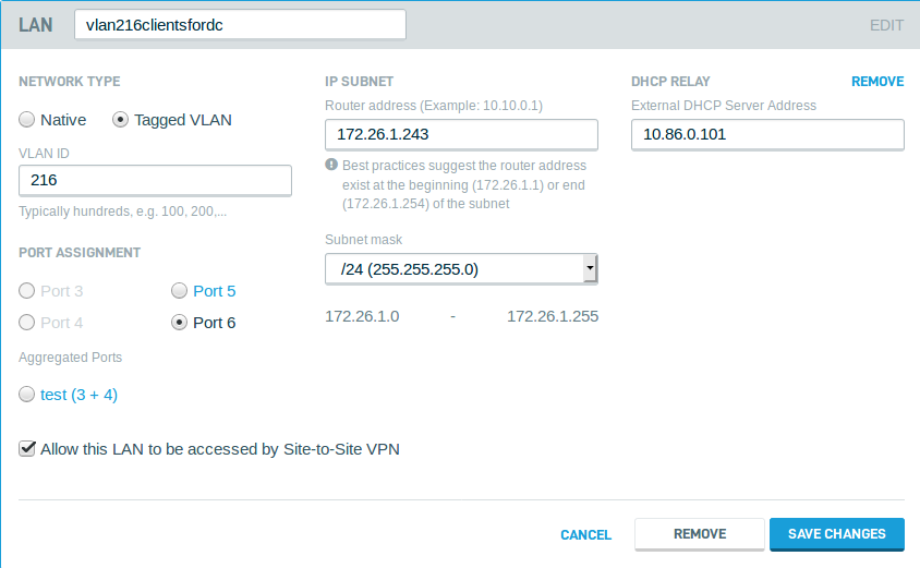
You can configure a DHCP server external to the DNA for more centralized management of client IP addresses. To activate this feature:
1. Select the DHCP Relay option below the desired LAN in the Networks pane (shown in Figure 2).
2. A DHCP Relay field will appear on the LAN card. In the input box, Enter the IP address of the DHCP server you would like the DNA to use, then click Save Changes.
Static DHCP Leases (Reservations) 
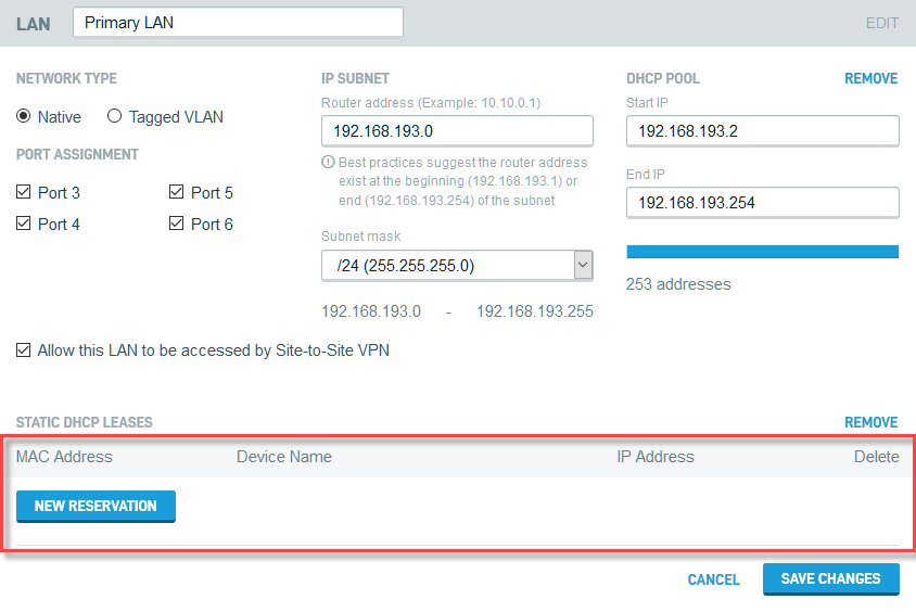
1. In the Networks pane (shown in Figure 2), select the Static DHCP Leases option below the desired LAN.
2. A Static DHCP section will populate on the LAN's configuration card. Click the New Reservation button, and complete the MAC Address, Device Name, and IP Address fields.
3. Click the Save Changes button.
LAN Site-to-Site VPN access

If a Site-to-Site VPN exists on the DNA, you can allow this LAN to be accessed by Site-to-Site VPN by selecting the respective checkbox as seen in Figure 10.
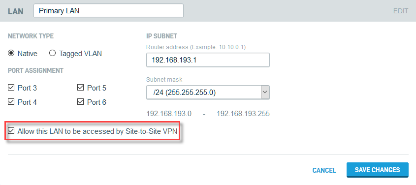
Figure 10: LAN Site-to-Site VPN access
Quality of Service (QoS) 
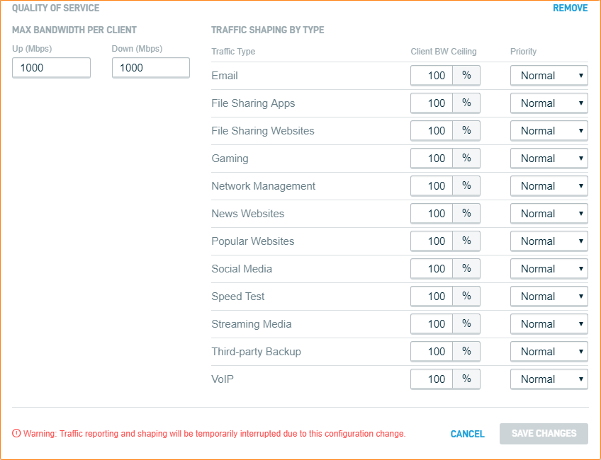
The Quality of Service option provides a method to create throttling and priority for specific traffic so that business-critical applications can work as expected while throttling other non-critical applications.
The Quality of Service option provides the following management features:
- Max Bandwidth Per Client: Allows you to define universal upstream and downstream bandwidth limitations for all clients accessing the Datto Networking Appliance. This value represents the maximum amount of bandwidth that a client with no additional restrictions placed on it by the device will be allowed to use.
- Traffic Shaping by Type: This field allows you to granularly throttle and prioritize network traffic based on its detected traffic type.
- The Client BW Ceiling field allows you to define the maximum allowable percentage of available bandwidth each type of traffic is permitted to use.
- The Priority dropdown allows you to prioritize bandwidth allocation to each type of network traffic. You can choose from High, Normal, or Low.
Note that High-Priority network traffic will be prioritized above Normal-Priority and Low-Priority traffic, even if the High-Priority traffic has a Client BW Ceiling value of less than 100%.
Advanced Options

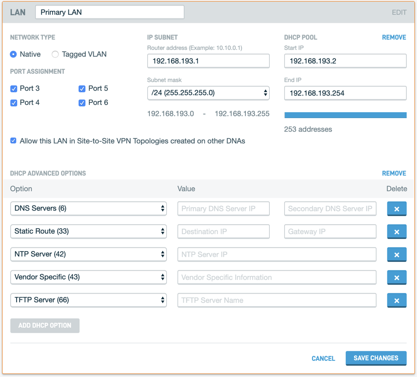
The Advanced Options card lets you specify the following configuration features:
- Network type: This option designates a LAN/VLAN as native or tagged.
- Port assignment: This option lets you assign a LAN/VLAN to a specific port on the DNA.
- IP Subnet: These fields let you specify a specific IP address and subnet mask for your LAN.
- DHCP Pool: These fields let you specify the IP range for your LAN.
- DHCP Advanced Options: These fields let you add and specify custom values for LAN components. You can configure the following options:
- DNS Servers (option 6): You can Enter IP addresses for a primary and a secondary DNS server in these fields.
- Static Route (option 33): You can use this option to specify the destination and gateway IP addresses for static routes.
- NTP Server (option 42): This option lets you specify an IP address for your NTP server.
- Vendor Specific (option 43): This field lets you add vendor-specific information for the DHCP server.
- TFTP Server (option 66): This option lets you specify a TFTP server name.

