AP440 quick start guide
Topic 
This article describes how to get started with the Datto Networking AP440 Access Point
Environment
-
Datto AP440 Access Points
Description
The Datto AP440 Access Point is designed for installation outdoors or indoors.
IMPORTANT This device does not support passive Power over Ethernet. Attempting to power it in this manner can result in hardware damage and may void your warranty.
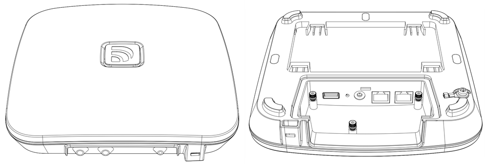
Figure 1: Access point overview
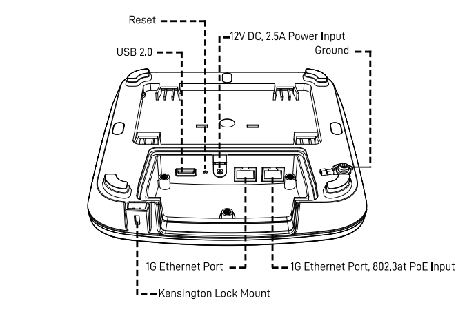
Figure 2: Access point connections
Index 
What's in the box
Your AP440 package should contain the following:
-
1 Datto AP440 Access Point
-
1 Port cover and gasket
-
1 Protective cable guide
-
5 M3-8 Port cover screws
-
1 Mounting brackets
-
1 12" Flat Ethernet cable
-
1 Blank LED tab
-
1 M4-6 grounding screw
-
1 Allen and torque combo tool
-
2 9/16" T-rail clip sets
-
2 15/16" T-rail clip sets
-
2 M3-10 T-rail clip screws
-
4 M4-25 Drywall screws
-
4 Wall anchors

Figure 3: Package contents
Installation considerations
This access point is designed to be installed either indoors or outdoors with several mounting position options. When mounting this access point, keep the following in mind:
-
802.3at PoE Input by PoE Switch or PoE Injector, or optionally by the 12V DC input jack. (Contact Local Dealer or Manufacturer for PoE Injector) Ensure that Protective earth grounding is available for the device:
-
Connect the power supply cord to a socket-outlet with earthing connection.
-
Using the factory-supplied grounding screw, mount an appropriately sized grounding wire from that grounding point on the chassis to a good earth ground.
-

-
The AP 440 WiFi-6 Access Point cannot be powered by passive PoE.
-
Place the access point at the center of the room, away from metallic surfaces.
-
The signal primarily radiates to the front and sides of the access point. There is limited signal coverage directly behind it.
-
Do not place heavy objects on the access point.
-
Install the access point in an area free from strong electromagnetic sources.
-
Check the Ethernet cables to ensure they are fully secured to both the access point and the PoE injector or switch.
-
Do not install the access point in plenum spaces. Use the ceiling mount instead.
-
Ethernet Port 1 is PoE input only. Ports do not include PoE passthrough and are not able to supply PoE to other devices.
-
Passive 24V PoE is not supported on this device. Do not plug 24V PoE into the access point. Damage can result.
-
Le PoE passif 24V n'est pas pris en charge sur cet appareil. Ne branchez pas sur le systéme. Des dommages peuvent en résulter.
Electrical hazard: Only qualified instructed or skilled personnel perform installation, repair, or disassembly procedures.Risques d'életrocution: Seul un personnel qualifé ou qualifié doit effectuer les procédures d'insallation, de réparation ou de démontage.
Assembling the protective port cover and cable guide
To best seal and protect the device, do not mount the it with the cable ports facing upwards.
1, Plug a rounded Ethernet cable into the Ethernet port on the far right side of the connection panel. This is the port with 802.3AT PoE input support.
2. Wrap the gasket around the Ethernet cable, alignit with the I/O cover spacing, and push it into place.
3. Position the plastic port cover over the gasket and use the provided Allen and torque tool to screw the 5 hex screws into place.
4. Use the plugs to fill the unused I/O ports.
Assembling the protective cable guide
1. Align the cable guide's mounting holes with the three screw mounts on the AP440's housing.
2. Using the provided Allen and torque tool, screw the three provided cover screws into place.
Wall or solid ceiling mount
You can mount the AP440 to any solid wall or ceiling.
1. connect the cables, and connect an Ethernet cable to the Ethernet port, with a 802.3at PoE source.
2. Install the protective cable guide using the port cover screws.
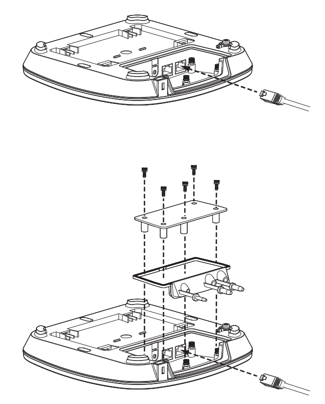
Figure 4: Port cover installation
1. Install the flat side of the mounting plate on a wall or solid ceiling with drywall screws and anchors (the arrow points up).
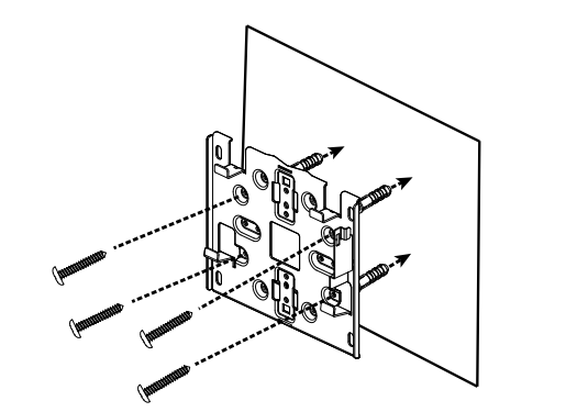
Figure 5. Mounting plate overview
2. Slide the Access Point onto the mounting plate and lock into place.

Figure 6. Mounting the Access Point to the wall clip
3. Align the mounting plate screws on the Access Point with the mount holes. Slide the device down onto the mounting plate, then secure the access point with the security screw. Finally, attach a grounding cable (not included).
T-rail ceiling mount
Use this mounting method to attach the access point to a drop ceiling T-rail, or other T-rail system.
1. Install the desired size T-rail clip set onto the mounting plate. Secure the clips with T-rail screws.
2. Install the mounting plate by pressing both clips onto the ceiling T-rail until fully engaged.
3. Connect the Ethernet cable to the access point's Ethernet port. If needed, connect a DC power source.
4. Align the access point and mounting plate, then slide the device towards the ports to lock in place.
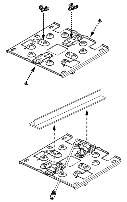
Figure 7: T-rail mounting
Ethernet or junction box mount
You can mount the AP440 to a junction box for secure installation in hotel guest rooms, dorms, care facilities and more.
1. Install the flat side of the mounting plate to the junction box.
2. Connect the Ethernet cable to the access point's Ethernet port. If needed, connect a DC power source.
3. Install the access point on the mounting plate and lock into place.

Figure 8: Junction box mounting
Pole mounting
Use the pole mount instructions to attach the AP440 to curved surfaces.
Pole mounting considerations
-
When pole mounting use maximum 1/2 inch-wide metal clamp cables (not included). Do not use plastic zip ties.
-
When pole mounting, install the AP440 with the ports facing toward the ground. Do not install with the ports facing upward.
Pole mounting procedure
1. Install clamp cables through the slots on the mounting plate.
2. Install clamp cabling (not included) through the slots on the mounting plate. The plate can accommodate clamp cabling up to 1/2 inch wide.

Figure 9: Pole mount attachment
3. Attach the clamp cabling around the pole.
4. Follow steps 2 through 5 of the Wall or solid ceiling mount instructions above.
Unmounting instructions
1. Press the lever on the top side of the Access Point to disengage it, then slide the access point away from the ports until it releases.
2. Remove the port cover and disconnect the Ethernet cable.

Figure 10: Device unmounting
LED light states
See LED indicator meanings for Datto Ap440, AP840, and AP840E access points to determine the LED light code meanings for this device.
Cloud management
To connect your access point to Datto Network Manager, follow the instructions in Setting up cloud management on DattoAP440, AP840, and Datto AP840 Access Points.


