AP840 quick start guide
This article describes how to get started with the Datto Networking AP840 Access Point
Environment 
-
Datto AP840 Access Point
Description
The Datto AP840 Access Point is designed for installation indoors.
IMPORTANT This device does not support passive Power over Ethernet. Attempting to power it in this manner can result in hardware damage and may void your warranty.

Your AP840 package should contain the following: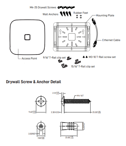
- 1 Datto AP840 Access Point
- 2 9/16" T-rail clip sets
- 2 15/16" T-rail clip sets
- 2 M3-10 T-rail clip screws
- 1 Ethernet cable
- 4 M4-25 drywall screws
- 4 wall anchors
- 4 rubber feet
- 1 blank LED indicator tab
This access point is designed to be installed indoors with several mounting position options. When mounting this access point, keep the following in mind:
- 802.3at PoE input or optionally a 48v DC 0.625A input jack.
- The AP840 WiFi-6 Access Point cannot be powered by passive PoE.
- Place the access point at the center of the room, away from metallic surfaces.
- The signal primarily radiates to the front and sides of the access
- point. There is limited signal coverage directly behind it.
- Do not place heavy objects on the access point.
- Install the access point in an area free from strong electromagnetic sources.
- Check the Ethernet cables to ensure they are fully secured to both the access point and the PoE injector or switch.
- Do not install the access point in plenum spaces. Use the ceiling mount instead.
- The 2.5G ethernet port is PoE input only. Ports do not include PoE passthrough and are not able to supply PoE to other devices.
- Passive 24V PoE is not supported on this device. Do not plug 24V PoE into the access point. Damage can result.
- Le PoE passif 24V n'est pas pris en charge sur cet appareil. Ne branchez pas sur le systéme. Des dommages peuvent en résulter.
IMPORTANT Electrical hazard: Only qualified instructed or skilled personnel perform installation, repair, or disassembly procedures.Risques d'életrocution: Seul un personnel qualifé ou qualifié doit effectuer les procédures d'insallation, de réparation ou de démontage.
-
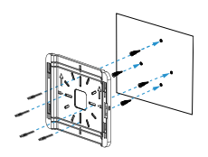
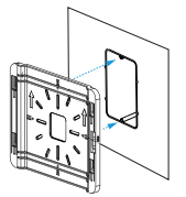
Attach the mounting plate to any solid wall or ceiling by placing the flat side against the surface and using the wall screws and anchors.
-
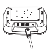
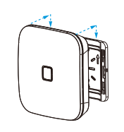
Connect the ethernet cable to the 2.5 G access port. Connect the DC power source if needed.
-
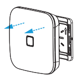
Align the access point with the mounting plate, then slide the device toward the ports until locked in place.
-
Install the desired size T-rail clip set onto the mounting plate. Secure the clips with T-rail screws.

-
Install the mounting plate by pressing both clips onto the ceiling T-rail until fully engaged.

-
Connect the Ethernet cable to the access point's 2.5 G port. If needed, connect a DC power source.
-
Align the access point and mounting plate, then slide the device towards the ports to lock in place.
You can mount the AP840 to a junction box for secure installation in hotel guest rooms, dorms, care facilities and more.
-
Install the flat side of the mounting plate to the junction box.
-
Connect the Ethernet cable to the access point's 2.5 G port. If needed, connect a DC power source.
-
Install the access point on the mounting plate and lock into place.
-
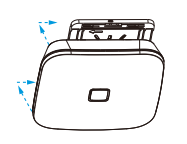
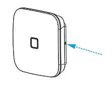
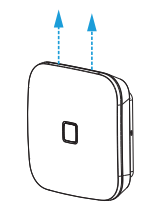
Insert a small flat screwdriver into the release hole on the side of the mounting plate.
-
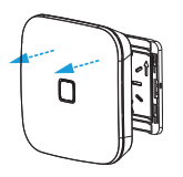
Slide the access point away from the ports until it disengages from the mounting plate.
-
Pull the access point away from the mounting plate and disconnect the cables.
To connect your access point to Datto Network Manager, follow the instructions in Setting up Cloud Management on AP440, AP840, and AP840E Access Points.


